artist stament.
While the internet has created new and efficient ways of communicating around the world, the Pandemic has taught us that the presence of self and identity becomes compromised through a predominantly online world. As humans, we rely on social interactions as a means to communicate and grow on a subliminal level. When taken apart, online interactions become the solution, however it comes at the cost of an interpersonal relationship between emotion and identity.
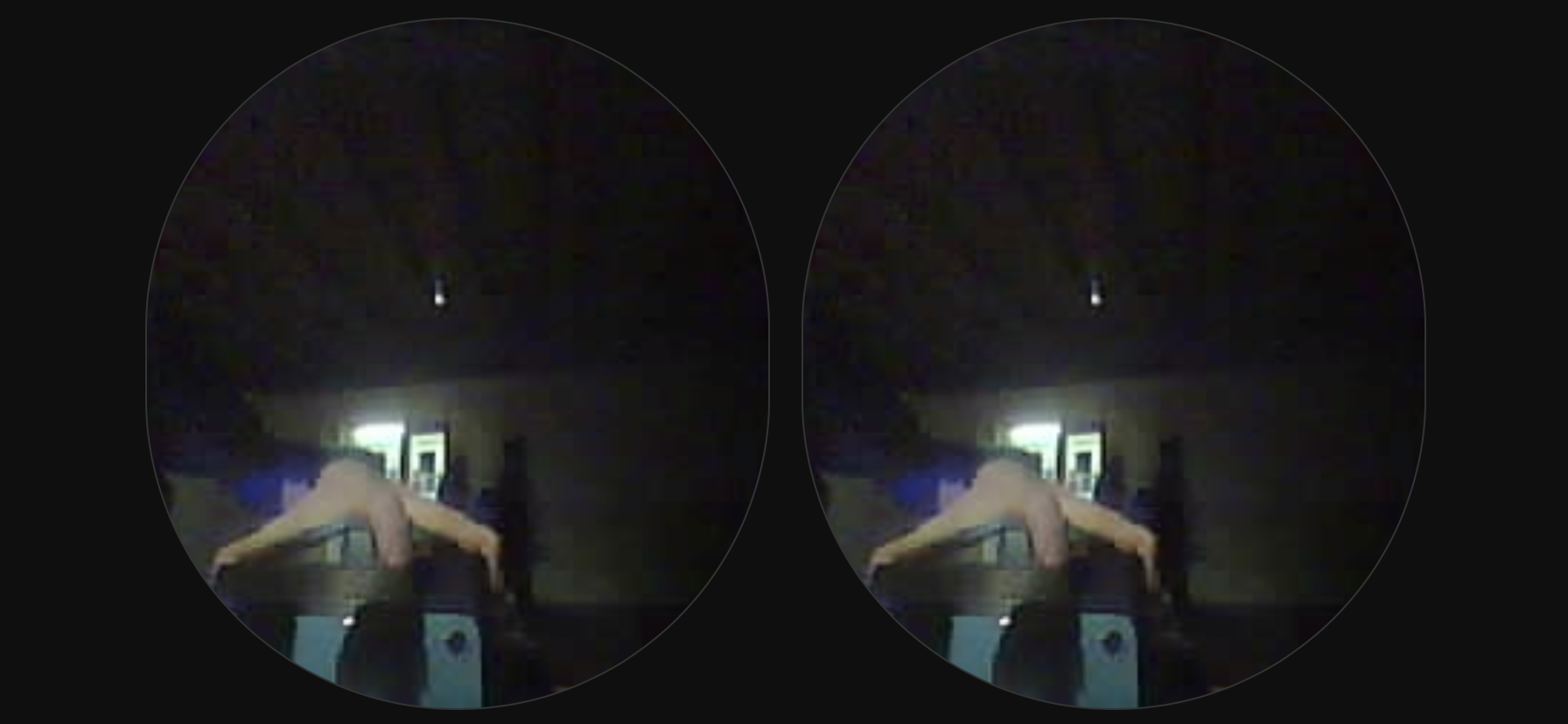
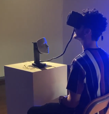
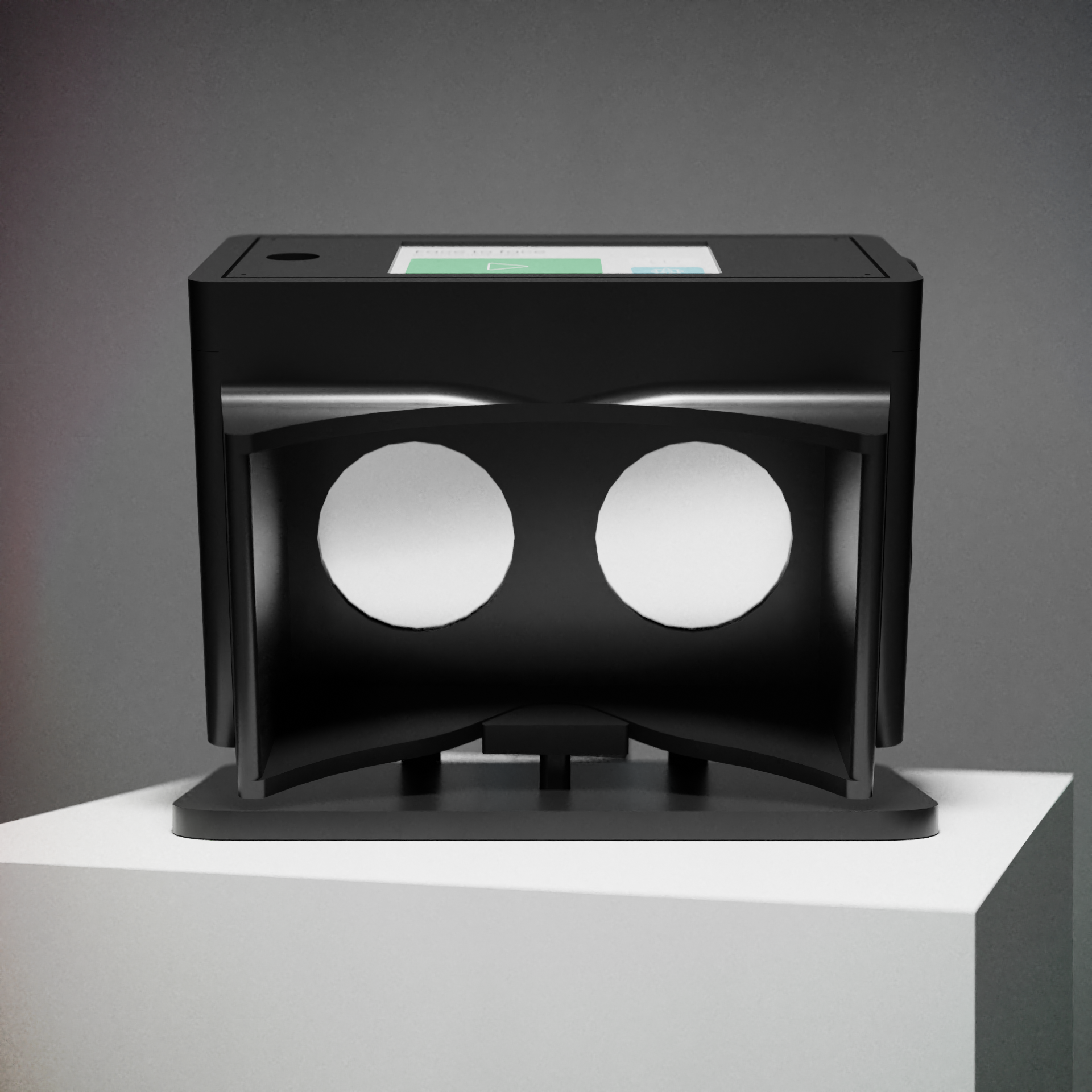
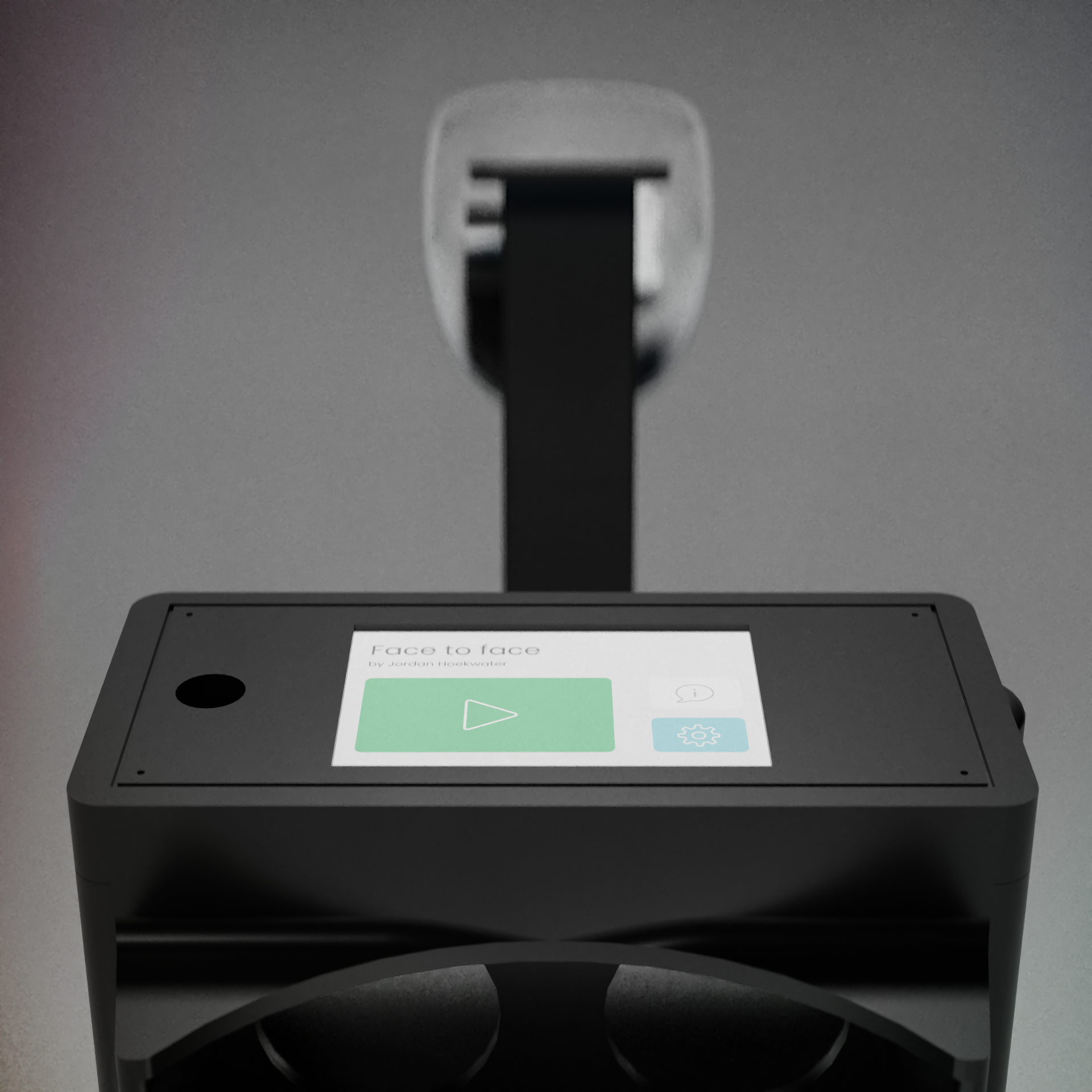
As a means to convey the necessity of online interaction brought out by the Covid Pandemic, this digital interface is made to disconnect the user from the sense of separation by giving them an augmented face to face interaction with their own digital identity. Face to face is an interactive reflection on the perceptual disconnection brought out by a socially restrictive environment and explores the interpersonal identity of a skewed presence through the internet. Since it’s initial change, people have been separated from one another to embrace a commercialized form of communication. The device displayed in the exhibition is modeled to be mass produced, utilizing 3D printing, readily available components, and the collaboration between peers. Each device is meant to divide the cognitive disconnection of social presence through online communication by placing the user in a virtual space to experience their own sense of identity through the internet.
documentation.
phase 1
3D Printing and Modeling Tests
For my BFA, I wanted to create an arduino bassed vr experience. I was familiar with the mechanics involved with a three axis gimbal and wanted to integrate the servos into proper enclosures while testing out the the 3D printer. I began planning out the system and considerations I needed to keep in mind during the modeling process. I wanted the device to have concealed wires to evoke the consumer side of the aesthetic, while looking pleasing to the eye. I began modeling the servo enclosures in Fusion 360 with an imported model of the SG90 motor to gauge the proper size of the motor.
Version 1 of the motor enclosure was unsuccessful, however the socket rotation for the enclosure fit together but wasn't able to rotate. I then reprinted the enclorsure with incremental gaps to give room for it to rotate. After another iteration, I was satisfied with the sizing, however, the z-axis for the point of rotation was off center from the point of rotation of the servo causing frition in between turns. Running the servo through some test code found that the enclosure's off center point of rotation prohibited it from being able to rotate. So, yet another iteration was modeled from the base up, ensuring that the z-axis would line up properly. I then remade the joinery to account for printing inconsistencies and semi rotational movements unaccounted by the z-axis. Since I was creating, more or less, a gimbal to rotate the head, I also modeled connections for the arms that would connect the gimbal together, ensuring their was enough room for wires to run through. I also did a rough sketch of the design for the enclosure while I was at work to begin modeling it.
I then duplicated and repositioned the joints along the three axis to model the arms. Initially, I modeled the joinery too far apart from one another without taking the size of the mask into consideration. I found a low poly mask online that I was initially going to base the face off of and positioned it along the axis to recreate the the arms. I started by repositioning the joints and remaking the arms to connect them together.
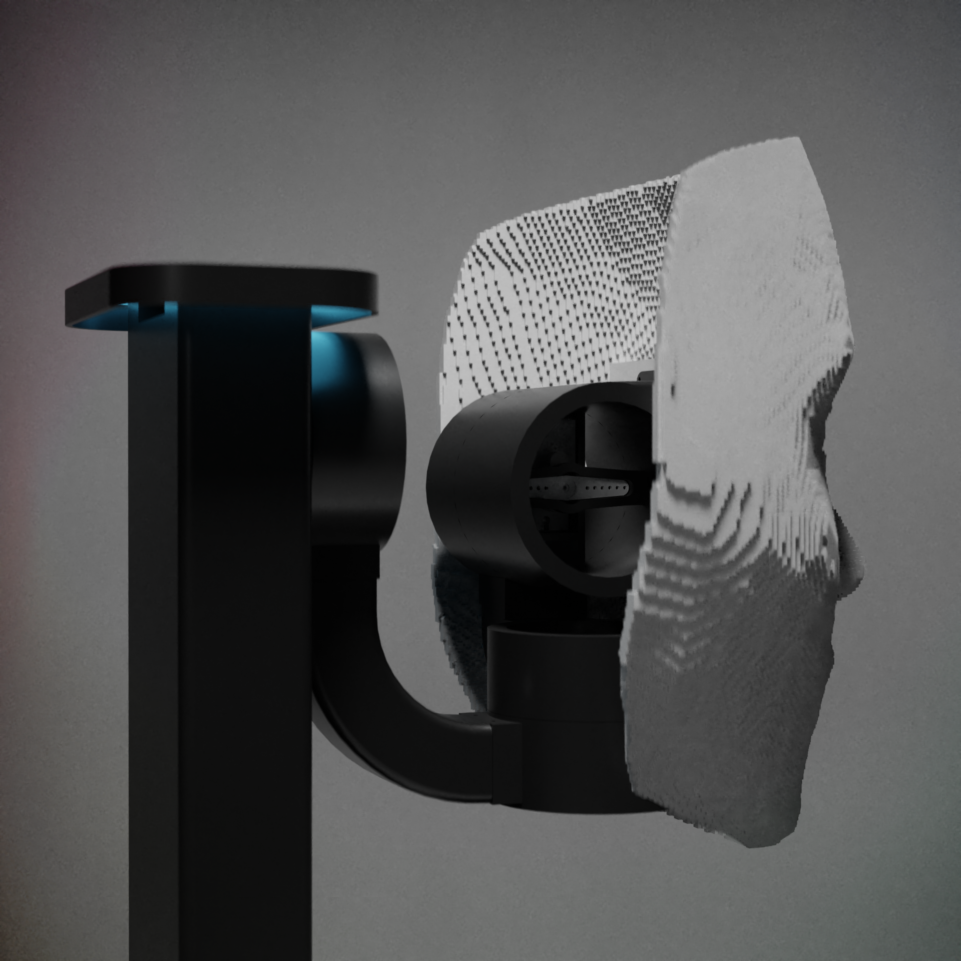
I then began modeling the base. The original idea for the gimbal was to be attached at the base to allow it to rotate with a full range of motion, however with some consideration, I found that fixing the gimbal along the z-axis would serve as a way to have a distinguishable front. This allowed me to build an arm that would serve as the mount for the y rotation of the gimbal and the addressible leds. Making the interior of the arm hollow allowed me to house the wires for the servos and leds coming from the base. For the base, I made a flat platform with interior housing for the arduino mega used in the project by adding mounting rods to allow you the screw the the board to the base upside down. Placing the power cable in the center gave just enough room for the wires that would connect to the headset. I then resized the plane to fit on the 3D printer and touched up the y-axis mount for the servo then added the gimbal.
After that I remade the arms to account for a smaller scaled mask for the device. I moved the joints closer together and created smaller arms that would printed more efficiently than the previous design. Keeping in mind, the prints need supports while creating an overlap so the design for the armature was made to not only print more efficiently, but to also maintain a high quality print. This made the gimbal a lot more compact allowing for a smaller scalled mask.
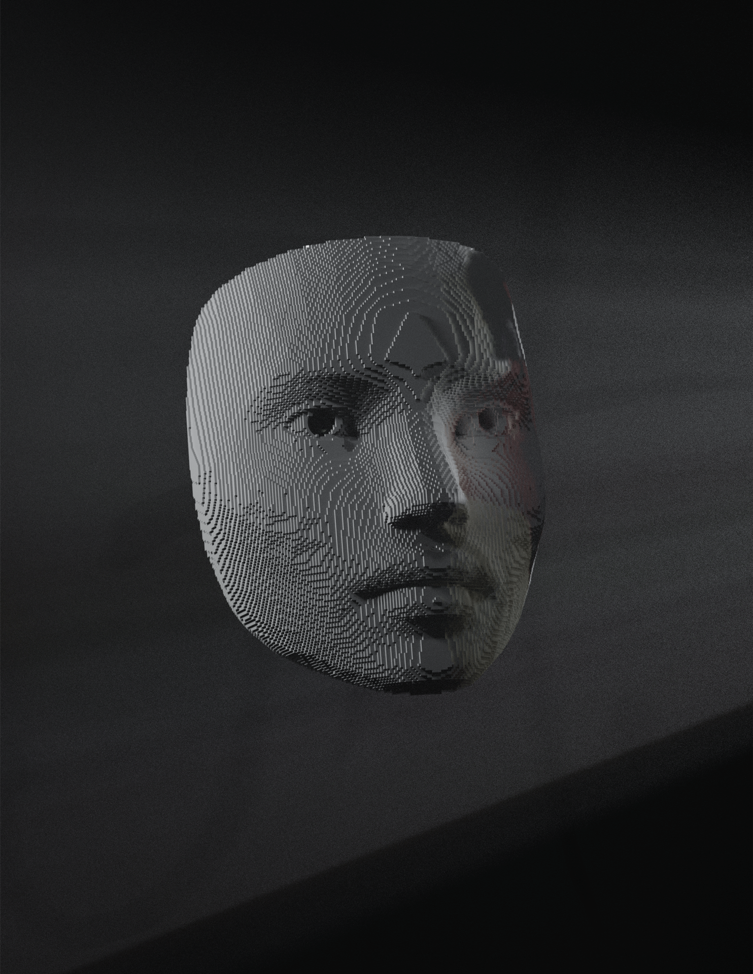
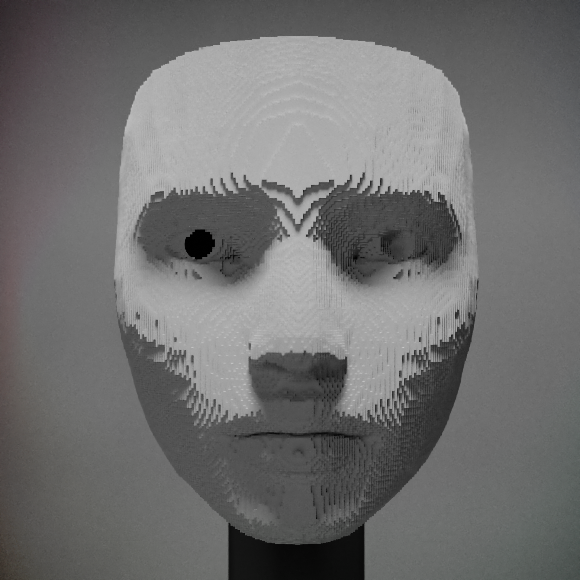
I then went into Blender to begin modeling the mask. I created a low poly base mesh to then modify using various modifiers resulting in a pixelated face. Once the mask was converted to an editable mesh in Fusion 360, I then orientated the mask and scaled it to an appropriate size for the gimbal. The placement also documented the degrees of freedom to allow the servos to limit their rotation.
I then placed a model of the ESP-32 CAM module to begin modeling the mount for the mask. The camera itself needed to be fixed to the mask in a way that would be accessible from the outside to program the camera separate from the MEGA. Cutting out a hole through the mask allowed for a wide angle lens to fit perfectly in the slot. I then fixed a horizontal bracket to the mask that would be a mounting surface for the y-axis rotation. The issue was, that the y-axis bracket needed to be mounted to the mask before being installed to the rest of the gimbal. So ensuring that the wing connected to the servo can be accessed after installation, the model stayed separate from the mask, however fastened using machine screws.
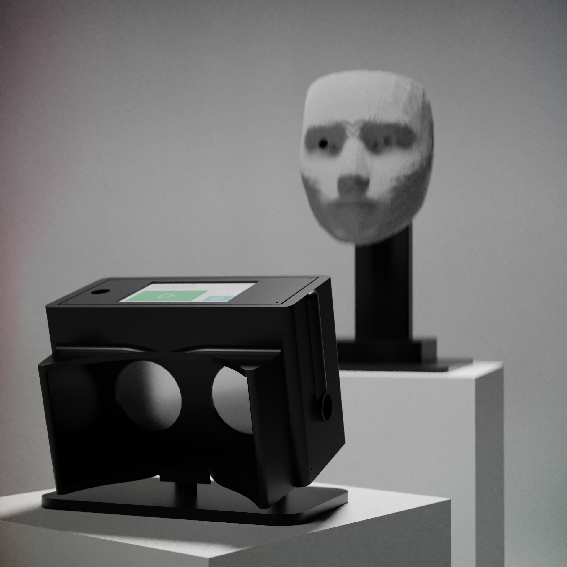
I then started modeling the vr goggles. I started with the measurements I jotted down from holding the fresnel lens over my phone and applied them to the first iteration of the goggles. I made sure to place all of the necessary components in the right spot and modeled the goggles around them. The first version ended up being very large due to the folding latch that would hold the phone. The form facter needed to be condensed down a bit to fit on the printer. Once the smaller version was done, I added strap holds for the headset and went to test out the print. The print ended up taking two and a half days to finish and also had a lot of supports inside hard to reach places. I did my best to remove them as carefully as possible but ended up breaking the lateral wall between the slot of the microphone and the fresnel lens. This was a major setback since I needed to make the headset print more efficiently. So I tore down the old design and focused on the important structual details. After that, I designed a planar version of the headset that would be held together by machine screws. Dividing the headset into planar pieces with no overlaps saved a day and a halfs worth of printing allowing me to quickly finalize a design and print it faster. After some minor cosmetic alterations, sizing fixes, and strap mount additions, I was able to finish the goggles quickly and start the printing process.
The device ended up looking pretty similar to what I had originally sketched out and was pleased with how it turned out. Since I finished the model, I began doing small renders for documentation for class progress.
3D printing went very smooth after all of the considerations I kept in mind during the print tests. All of the gaps, and joinery fit together nicely and I surprisingly didn't run into other complications with the prints after those initial errors.
phase 2
Code Tests and Program Development
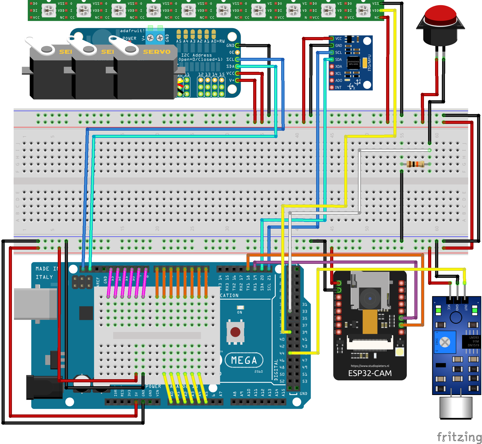
Since the model was complete, I was able to begin coding the prototype while the models were printing. I began by installing all of the necessary libraries for my components and testing to make sure they were working properly. Most of the devices were in working order, so I began merging the libraires into a master file for the project to run off of. I had alot of issues with the TFT LCD display running with some of the other components since the power needed to run the touch screen outweighted the power needed to run the others properly. Once I managed to get the code working for the display I began mapping out the internal schematics for the device. I then began working on assembling the prototype for the test code.
phase 3
Assembly and Software Fixes
After running the test code, everything seemed to be working properly together, so I moved forward with creating the two boards used in the final design. Making the boards as compact as possible, I soldered the new connections to reroute the TFT LCD, the MPU 6050, the sound sensor, and the momentary button to the vr goggles. This brought out a few major flaws with the initial design due to the power regulation between the device itself and the headset. After much deliberation and research, I found a solution to the issue without having to change too much of the prototype. This allowed me to move forward with assembly.
phase 4
BFA Exhibition Installation
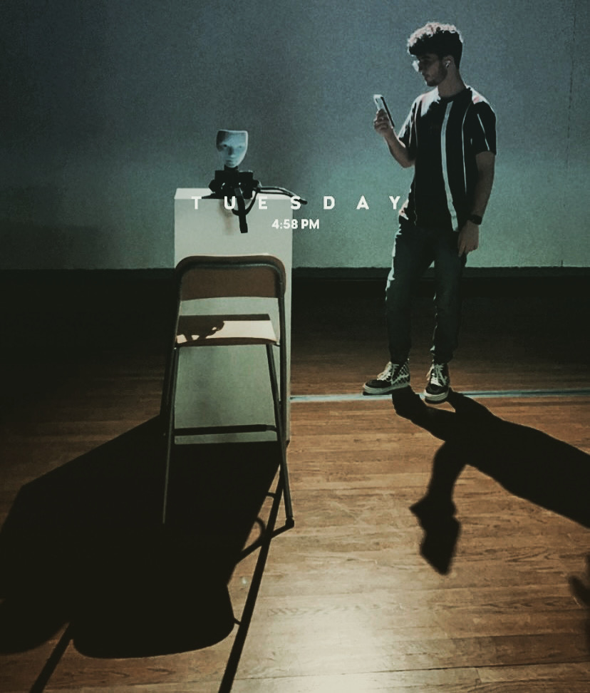
The exhibition took place Novemeber 08, 2021 - Novemeber 12, 2021 at the Art Building at San Jose State University. I had the device as the center piece in the gallery with two lights shining from the rear of the deivce, illuminating the user when interacting with it. Overall the exhibition was successful and I recieved a lot of good feedback.